Traffic Management Centre Networks
Network architecture for traffic management centres integrating video, control systems, and data for operational decision-making.
Highway backbone networks carry traffic data, control signals, and safety communications across extensive road networks – requiring reliability that matches the critical nature of transportation safety and efficiency.

Highway networks integrate traffic management, safety systems, and traveller information – communication failures create operational blind spots that affect safety and traffic flow.
Modern highways deploy numerous intelligent transport systems (ITS): traffic monitoring cameras, variable message signs, incident detection, weather stations, and tolling systems. These systems depend on continuous communication to central management. Network failures mean operators cannot see conditions or control roadside equipment.
Effective backbone design starts with reliability requirements for each system. Network architecture then implements appropriate redundancy and resilience. Environmental challenges include long distances, harsh weather, and physical exposure along road corridors.

Highway fibre optic networks provide reliable backbone communications for ITS systems.
Fibre optic cables along highways provide high-bandwidth, reliable communications for intelligent transport systems, with installation considerations unique to road corridors.
Highway fibre typically runs in the road reserve or median. Installation methods include direct burial, duct installation, or directional drilling. Cable selection considers environmental factors: temperature extremes, moisture, and potential damage from maintenance activities.
Network architecture uses ring topologies for resilience – a cable cut affects only one segment. Access points at regular intervals connect roadside equipment. Redundancy often includes diverse fibre paths or wireless backup. Partners like FlexDSL can extend connectivity using existing copper where fibre termination isn't practical.
The choice of fibre type—single-mode for long distances or multimode for high-density data centres at interchanges—impacts future scalability. Proper planning includes not just the initial installation but also maintenance access points and clear documentation of the fibre plant. This ensures that future expansion or repairs can be executed without major disruption to the highway or its communications.
Throughput Technologies advises on the complete lifecycle of highway fibre networks. We help specify cable types with adequate tensile strength and crush resistance for their environment. Our designs include detailed plans for handholes, splice locations, and network demarcation points that align with road maintenance schedules and future ITS expansion projects.
Wireless networks provide connectivity to roadside equipment where fibre isn't available, requiring careful design to ensure reliability in the mobile highway environment.
Microwave, cellular, and dedicated wireless systems connect cameras, signs, and sensors to the backbone. Line-of-sight requirements, frequency selection, and interference management affect reliability.
Wireless design considers equipment placement, antenna height, and path diversity. Redundancy often uses multiple technologies: primary wireless with cellular backup. Performance monitoring detects degradation before complete failure.
For point-to-point microwave links, path analysis is critical. Factors like Fresnel zone clearance, signal attenuation due to weather (rain fade), and potential future obstructions from vegetation or construction must be modelled. In urban corridors, licensed frequencies help avoid interference from other wireless systems, while in remote areas, the focus shifts to maximising range and minimising power consumption.
Our approach integrates wireless as a complementary layer to the fibre backbone. We design hybrid networks where fibre forms the primary trunk, and wireless provides spurs to difficult-to-reach equipment or acts as a failsafe redundant path. This ensures that a single technology failure does not isolate critical safety equipment like emergency telephones or avalanche monitoring systems in mountainous regions.
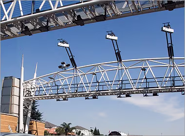
Dynamic message signs and lane control signals require deterministic communications to deliver timely information to drivers, with reliability directly affecting road safety.
Variable message signs display speed limits, warnings, and travel information. Lane control signals manage traffic flow during incidents. Network delays affect message timeliness – outdated information can be dangerous.
Network design guarantees maximum latency for sign updates. Redundancy ensures continuous operation. Security prevents unauthorised sign changes that could cause confusion or accidents.
The control protocol used is as important as the physical network. Systems should support both scheduled updates and immediate overrides for incident management. The network must prioritize these control commands over less critical data traffic. We implement Quality of Service (QoS) rules that mark sign control traffic as high-priority, ensuring it is never queued behind routine data transfers.
Throughput Technologies designs these networks with a focus on fail-safe states. If communications are lost, signs should default to a pre-defined safe message (like a blank screen or a generic caution message) rather than displaying potentially misleading or stale information. This network-level logic, combined with local controller intelligence, creates a robust safety layer.
Traffic monitoring networks collect data for management and traveller information.
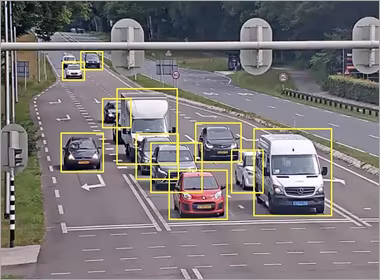
Traffic cameras, sensors, and detection systems generate data for management and traveller information – networks must deliver this data reliably while handling varying loads.
Cameras provide visual monitoring and incident verification. Sensors measure traffic flow, speed, and classification. Data volumes vary: continuous video streams versus periodic sensor data.
Network design accommodates both continuous and burst traffic. Bandwidth management prioritises critical data during incidents. Storage and processing architecture affects network requirements – edge processing reduces backbone traffic.
A major challenge is data tsunami during peak hours or major incidents. Network switches and routers must have sufficient buffers and intelligent traffic shaping to prevent packet loss. We architect networks with regional aggregation points. Raw video from multiple cameras can be processed locally at a roadside cabinet to extract metadata (e.g., vehicle count, average speed), which is then sent over the backbone, drastically reducing bandwidth needs.
We also design for data integrity. Sensor data for traffic modelling must be time-synchronised and complete. Network Time Protocol (NTP) servers and precision timing protocols ensure data from inductive loops, radar sensors, and Bluetooth trackers can be accurately correlated across the highway network, providing a reliable picture for traffic engineers.
Road weather stations monitor conditions affecting safety – networks must deliver this data reliably for timely winter maintenance and traveller warnings.
Weather stations measure temperature, precipitation, wind, and road surface conditions. Data informs maintenance decisions and public warnings. Communication failures mean decisions based on outdated information.
Network design considers remote locations and harsh conditions. Redundancy ensures data delivery during storms when it's most needed. Integration with forecasting systems improves predictive capabilities.
These systems are often in the most exposed and hard-to-reach locations: high mountain passes, long bridges, or remote stretches. The network design must account for extreme temperatures, ice accumulation on antennas, and power availability. Solar-powered stations with battery backup require networks with low-power sleep modes and efficient data transmission protocols to conserve energy.
Our designs implement store-and-forward capabilities at the network edge. If a connection is lost during a blizzard, the roadside controller stores sensor data locally. When the link is restored, it transmits the historical data, ensuring no gaps in the weather record. This is critical for understanding frost formation rates or salt dilution over time, directly impacting the safety and cost-effectiveness of winter maintenance operations.
Tunnels and bridges present unique communication challenges – enclosed spaces, structural considerations, and safety requirements demand specialised network design.
Tunnel communications include safety systems, ventilation control, lighting, and traffic management. Redundancy is critical – failures in enclosed spaces have serious consequences.
Network design includes diverse cable routes, fire-rated cabling, and backup systems. Equipment must survive harsh environments: moisture, vibration, and temperature variations. Safety systems often have dedicated networks.
In tunnels, radio frequency (RF) propagation is problematic. Leaky feeder cable systems are often deployed to provide consistent cellular and emergency service radio coverage throughout the length. These systems must be integrated with the backbone network for control and monitoring. The backbone itself typically runs in separate, fire-resistant conduits on each side of the tunnel, with automatic switching to the surviving path if one is damaged.
For long bridges, the physical movement of the structure is a key factor. Cables must be installed with sufficient slack and in conduits that allow for expansion, contraction, and vibration without causing stress fractures. Wireless bridges between the anchorages and the main span can sometimes provide a more resilient solution than running physical cables along the entire flexing deck. Throughput Technologies specialises in these complex, structure-dependent designs, ensuring communications resilience matches the engineering resilience of the asset itself.
Throughput Technologies advises on highway communications backbone design that balances performance, reliability, and cost for transportation applications. We help you navigate the complexities of long-distance fibre, hybrid wireless, and the integration of diverse ITS subsystems into a coherent, manageable, and future-proof network.
Talk with a Solutions Specialist to design your highway communications infrastructure.
Direct burial is common for new construction, placing cable 1–1.5 metres deep. Directional drilling minimises surface disruption for crossings. Duct installation provides protection and allows future cable additions. The choice depends on soil conditions, traffic management requirements, and long-term maintenance considerations. Always install spare ducts for future expansion – adding capacity later costs significantly more. For retrofits along existing highways, trenchless techniques like guided boring are essential to maintain traffic flow and reduce safety risks.
Use licensed frequencies where available to minimise interference. Ensure clear line-of-sight between antennas. Implement path diversity with redundant links. Monitor signal quality continuously to detect degradation. Deploy equipment with appropriate environmental ratings for roadside conditions. Always include backup connectivity – cellular or satellite – for critical systems. Additionally, design networks with a margin for signal fade; a link operating at 99% capacity in clear weather will fail in heavy rain. Regular path surveys are needed as vegetation grows or new structures are built.
Message sign updates should complete within 5–10 seconds from operator action to sign display. Faster updates (2–5 seconds) are needed for dynamic lane control signs during incidents. The network must guarantee these maximum latencies even during peak traffic conditions. Test under worst-case scenarios to verify performance. This includes simulating backbone link failures and switchovers to ensure the latency service level agreement (SLA) is maintained during network re-convergence events.
Modern traffic cameras with H.264 compression need 2–4 Mbps for continuous streaming at 1080p resolution. During incidents, multiple cameras may stream simultaneously to verify conditions. Edge processing (motion detection, license plate recognition) reduces bandwidth needs by sending only event data rather than continuous video. When designing backbone capacity, plan for the aggregate load of all cameras in a sector, plus a significant overhead for incident response and future higher-resolution (4K) upgrades.
Tunnel safety systems require dual diverse cable routes – typically on opposite sides of the tunnel. Equipment redundancy includes backup power supplies and control systems. Critical communications should have wireless backup that survives cable damage. Regular testing ensures failover works when needed. Document and maintain separation between redundant systems. Furthermore, consider the failure domain: ensure the primary and backup paths do not share common points of failure, such as the same power feeder, cable duct at the portal, or network aggregation switch.
Network architecture for traffic management centres integrating video, control systems, and data for operational decision-making.
Networking for electronic toll collection, violation enforcement, and toll plaza communications with reliability requirements for revenue collection.

Protecting transportation networks from cyber threats while ensuring operational continuity through segmentation, secure access, and resilient design.